The 2026 FIFA World Cup will expand to 48 teams. There will be more “fast runners” on the pitch than ever before. But no coach would ever allow every player to act on their own. Once teamwork falls apart, even the most talented players can be defeated by chaos.
The same logic applies to paralleling SiC power devices.
When a single device can no longer handle high current, paralleling becomes inevitable. But does simply soldering several devices together solve the problem? Of course not. Static current imbalance, dynamic current hogging, thermal runaway, gate crosstalk — any one of these issues can cause the system to collapse within milliseconds.
So, how can we make these “lightning-fast runners” move in perfect sync?
1. Why Must SiC Devices “Work as a Team”?
- Flexible configuration: Instead of spending heavily on customized high-current modules, standard discrete devices can be arranged like pieces on a tactical board. Capacity expansion becomes easier and more flexible.
- Distributed heat dissipation: Heat is no longer concentrated in a single device. Thermal design becomes easier, reducing the risk of local overheating and failure.
- Better cost-performance ratio: Purchasing standard devices in volume is usually more cost-effective than developing large customized chips or modules. Inventory management is also simpler.
- Redundancy potential: If one device fails unexpectedly, the remaining devices may still continue operating at a derated level — provided that the system has been designed for this scenario in advance.
- Higher power capacity: Large power electronic systems require higher current capability. Since the current rating of a single SiC module is limited, paralleling multiple devices can significantly increase the total current-carrying capacity of the system.
It sounds simple. But once several ultra-fast SiC devices are connected together, the real challenges begin.
2. The Challenges of Paralleling: It Is Not Just About Soldering Devices Together
On the football field, the worst situation is when one player is sprinting while another is barely moving. In SiC paralleling, the biggest obstacle is current imbalance — in simple terms, “some devices do all the hard work while others enjoy the ride.”
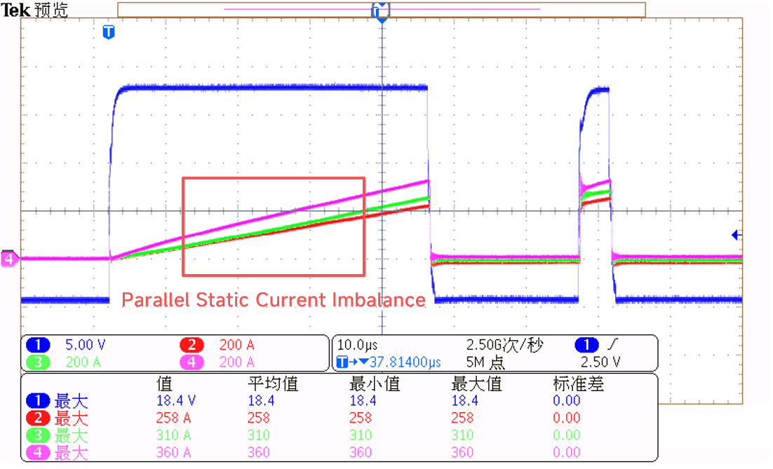
2.1. Static Imbalance: Natural Differences Between Devices
No two devices have exactly the same on-resistance or transconductance.
After paralleling, when all devices are fully turned on, how is the current shared? It is distributed according to the inverse of their on-resistance. The device with lower resistance carries more current, while the device with higher resistance carries less.
The same applies to transconductance. Two devices may receive the same gate voltage, but if one has higher transconductance, its current will rise more sharply once the gate voltage exceeds the threshold. As a result, under the same gate voltage, the device with higher transconductance will naturally take more current.
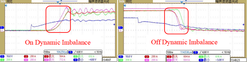
2.2. Dynamic Imbalance: The Most Dangerous Moment Is During Switching
SiC devices switch at nanosecond speed. Even small differences in threshold voltage can cause one device to turn on earlier than the others. The device with the lower threshold voltage starts conducting first and “takes the job” ahead of the rest.
At the same time, even tiny differences in parasitic inductance can lead to serious turn-on and turn-off mismatch.
2.3. Thermal Positive Feedback: The Hotter It Gets, the More It Grabs
There is a common misunderstanding about temperature.
When one device carries more current, its temperature rises. As the temperature increases, its on-resistance also increases. In theory, this should reduce its current share and create negative feedback, which helps current balancing.
However, SiC has a tricky characteristic: its threshold voltage decreases as temperature rises.
This means that the device carrying more current becomes hotter, its threshold voltage drops, and during the next switching event it becomes even more eager to conduct earlier and take more current. The temperature rises further, the threshold drops further, and the cycle continues.
Eventually, this can lead to thermal runaway — one device fails and may take the others down with it.
2.4. The Driver Challenge: The “Coach” Behind the Team
After multiple devices are paralleled, the total gate capacitance increases significantly. The driver must provide higher peak current.
Under nanosecond switching conditions, differences in PCB traces and parasitic inductance can easily cause switching mismatch. At the same time, a low-impedance turn-off path is required to suppress Miller crosstalk, and the system must ensure that the failure of one device does not drag down the entire driver circuit.
In addition, during high-speed switching, circulating currents may appear between paralleled devices. These devices may “interfere with each other,” increasing the risk of gate oscillation and false turn-on.
This places much higher requirements on gate signal consistency, driver layout symmetry, and power supply stability.
3. Three Sets of “Coach’s Tactical Boards”
The gate driver is the core controller of SiC switching, the head coach of the paralleled SiC system. If we want every player to perform at their best, an excellent coach is indispensable.
So, how can we make a paralleled driver stable and reliable?
Let us look at several “Coach’s Tactical Boards”.
3.1: Passive Solution
One driver IC drives several SiC devices, and their gates are directly connected together.
In this solution, several issues exist:
- Insufficient drive current: When several devices are connected in parallel, the total gate charge multiplies. However, the peak current capability of the driver IC is fixed. If the peak drive current cannot meet the demand of the paralleled devices, switching loss will increase.
- Mutual crosstalk: When the gates are directly connected, the Miller voltage spike generated during the turn-off of one device may be coupled directly into the gate of a neighboring device through the shared gate connection. This may cause false turn-on or even gate damage.
- Severe circulating current: During high-speed switching, SiC devices are highly sensitive to parasitic inductance. Under high di/dt and dv/dt conditions, differences in loop inductance cause different coupled voltages in the gate loops. The paralleled devices may interfere with each other.
If the gate of one device fails and becomes shorted to ground, the entire driver voltage may be pulled down instantly, affecting all devices.
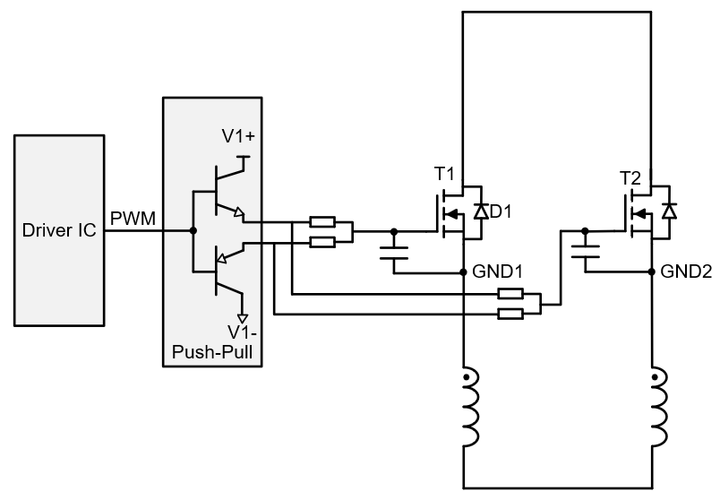
3.2: Traditional Active Solution
In this solution, each SiC device is equipped with an independent push-pull driver stage, but all push-pull stages share the same power supply and common ground.
- Advantage 1: Each SiC device has its own dedicated push-pull output stage. Every channel can provide sufficient peak current independently, allowing the switching capability of each device to be fully utilized. The turn-on and turn-off process of each channel becomes relatively independent.
- Advantage 2: In the active solution, each device has its own push-pull driver. During turn-off, the low-side transistor provides a very low-impedance path, bypassing the coupled current to ground. As a result, the gate voltage is less likely to rise, reducing the risk of false turn-on.
- But One Problem Remains: The circulating current problem is still not fully solved. Both the traditional passive and active solutions use the same power supply for all push-pull stages. In the high-speed and high-frequency operating environment of SiC, this structure still cannot effectively suppress circulating currents between paralleled devices.
If one device has a gate-related fault, it may still affect the entire group.
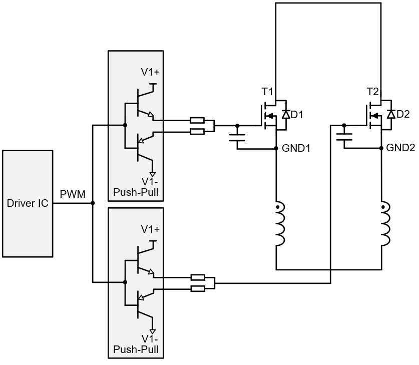
3.3: Circulating Current Suppression Solution
In this solution, each SiC device is equipped with an independent push-pull driver, and each driver channel has its own independent isolated power supply.
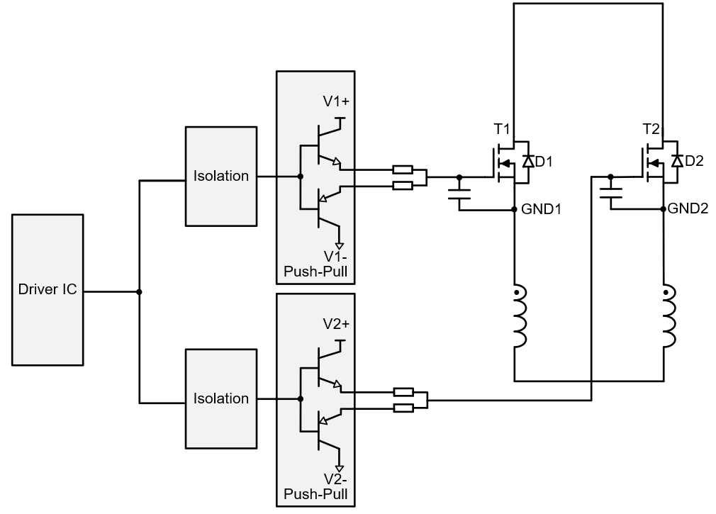
- Advantage 1: Each driver unit has its own isolated power supply. If the gate of one device is shorted, the other driver units can continue operating normally without being affected.
- Advantage 2: Each driver unit has an independent ground reference. There is no direct electrical connection between gate loops. The conductive path is physically cut off.
- Miller crosstalk spikes, switching oscillations, and circulating currents generated by one device are confined within its own loop. They have no path to enter the gate loop of neighboring devices.
- Advantage 3: In the circulating current suppression solution, each driver unit has its own floating ground, which is not directly connected to the power ground. The noise coupling path is isolated and cut off, resulting in stronger common-mode noise immunity.
4. The Role of the Isolated Power Supply
In a circulating current suppression parallel solution, an excellent isolated power supply is essential.
The 2FB02PxxxxxMPT series is a SiC MOSFET weak-isolation DC-DC converter independently developed by FSD. This series is designed for single-channel driver power supply applications and provides an additional output for IC power supply, features a wide input voltage range, high output accuracy, and ultra-compact design.
Advantages:
- Primary-to-secondary insulation: 2 kVDC
- Total output power: 2 W
- Wide input range: 10–30 V
- Wide output range: 20–25 V
- Ultra-compact: 12 mm × 12 mm
- Output overcurrent protection, output short-circuit protection, and over-temperature protection
- Primary-to-secondary coupling capacitance: 10 pF
Typical Applications:
- Energy storage
- Industrial drives
- Photovoltaic
- Rail transit
- BMS power supply
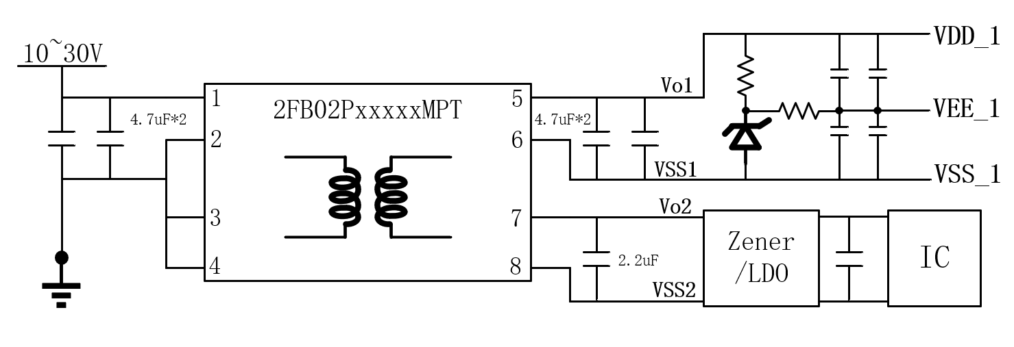
Recommended Circuit
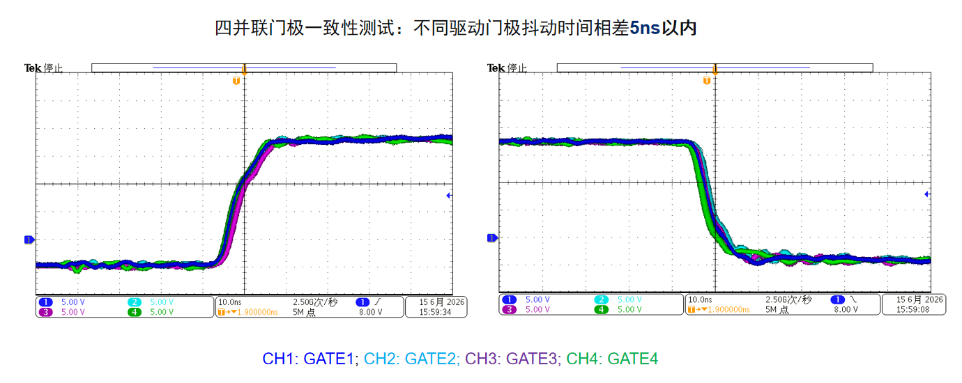
Parallel Application Test Waveforms
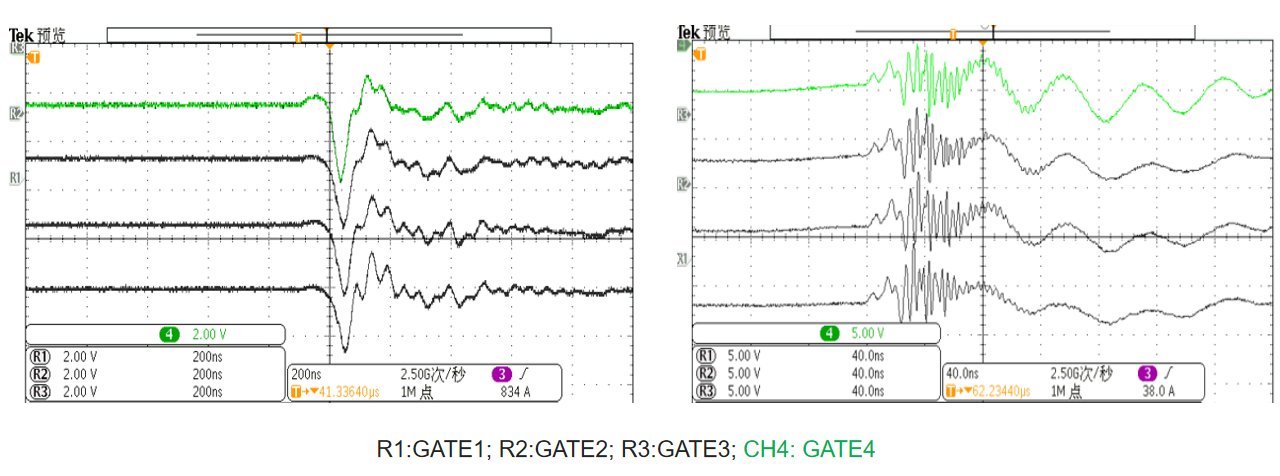
1. Four-Parallel Gate Consistency Test: The gate timing skew between different driver channels is within 5 ns, and the drive voltage deviation is less than 0.3 V.
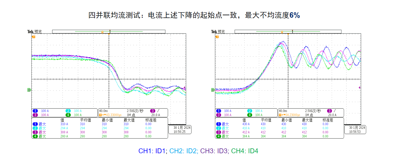
2. Four-Parallel Current Sharing Test: The starting points of the current rise and fall are consistent, and the maximum current imbalance is 6%.
3. Gate Crosstalk Test of Four Paralleled Devices: The crosstalk voltage is consistent. There is no circulating current coupling between the gates, and none of the gate voltages exceeds the maximum limit.
SiC paralleling has never been a question of whether it should be done. In the era of high power, it is a must-answer question.
From passive solutions to circulating current suppression architectures, driver solutions continue to evolve. Reliable current sharing does not rely on luck — it relies on architecture.
A well-designed driver architecture keeps faults outside the system, blocks noise behind the wall, and synchronizes every SiC device to switch in the same rhythm.