In IGBT applications, gate oscillation is one of the most common challenges. It not only affects switching performance but can also trigger overvoltage, overheating, or even device damage. The causes of oscillation are diverse, primarily including:
- IGBT's own parasitic parameters
- Improper drive circuit design
- Power supply voltage fluctuations
- Temperature variations
- External electromagnetic interference
- Device aging
If external interference is excluded and analysis focuses solely on the drive circuit itself, gate oscillations can be primarily categorized into three types:
- Turn-on oscillations
- Turn-off oscillations
- Short-circuit oscillations
Among these, turn-off oscillations and short-circuit oscillations are often collectively referred to as RF oscillations.
I. Oscillation During Turn-On
During the IGBT turn-on process, oscillation in the gate driver waveform typically arises from the following causes:
1.1 Insufficient Drive Capability
If the drive current is too low, slow charging of the Miller capacitance CGC may induce oscillation during voltage ramp-up.
Solution:
Appropriately reduce the gate resistance RG to increase the drive current. Generally, adjusting it to 0.6–0.8 times the original value and verifying through testing is recommended.
1.2 Oscillation Caused by Parasitic Inductance in the Drive Circuit
The parasitic inductance Lp in the drive circuit forms an LC resonant circuit with the IGBT's input capacitance Cies, which is prone to oscillation under switching excitation.
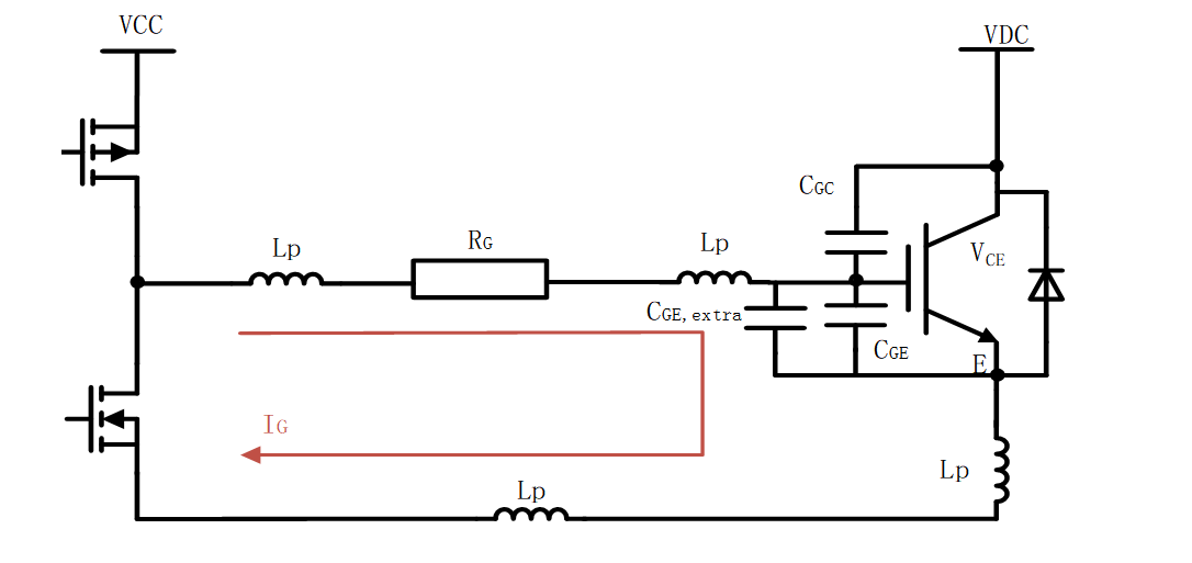
Solutions
- Optimize PCB layout to shorten drive loops and reduce parasitic inductance.
- While meeting switching speed requirements, connect an appropriate capacitor CGE,extra between GE terminals to alter the resonant frequency and suppress oscillations.
1.3 Excessive DC Bus Stray Inductance
Bus stray inductance Lp generates voltage spikes during switching, which couple and affect gate signals.
Solutions:
- Optimize bus structure using laminated or low-inductance busbar designs.
- Parallel non-inductive snubber capacitors between CE to suppress voltage overshoot.
II. Radio Frequency Oscillation
When the IGBT operates in the amplification region, it forms a feedback loop with parasitic parameters. If the feedback signal exhibits phase shift, positive feedback may occur, triggering high-frequency oscillation. The figure below illustrates an oscillation circuit formed by CGC, CGE, CCE, and stray inductance LG.
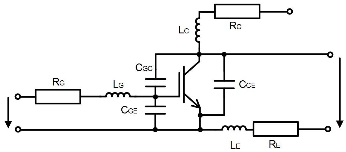
The IGBT and parasitic components form an LC oscillation circuit
2.1 Turn-off Oscillation
During turn-off, the dVCE/dt variation induces displacement current IGC through the Miller capacitance, which is fed back to the gate. Particularly during hard turn-off with high collector current IC, the Miller capacitance (CGC) increases with current magnitude, making oscillation more likely to occur.
The following table lists the primary parameters influencing oscillation during IGBT turn-off.
| Oscillation Type | Moment of Oscillation | Oscillation Frequency | Influencing Factors |
| Turn-off oscillation | Miller plateau during the turn-off process | Approximately several tens of MHz | Gate Resistance, Module-Packaged IGBT Parameters, dVCE/dt, IC |
Recommendations for Addressing the Issue:
If the oscillation amplitude is small and occurs sporadically, no immediate action is required. If the oscillation is frequent or exhibits a large amplitude, appropriately adjust the gate resistor.
2.2 Short-Circuit Oscillation
This section primarily addresses a specific type of short circuit (where the IGBT is already in a short-circuit state before turn-on). After the short-circuit current stabilizes, significant oscillations may occur in the gate voltage VGE, the collector-emitter voltage VCE, and the collector current IC.
| Moment of Oscillation | Oscillation Frequency | Influencing Factors |
| After the short-circuit circuit stabilizes | 10~20MHz | Internal structure of the module, IGBT characteristics, low VCE, high VGE |
Suppression Method:
Increase gate resistance RG to enhance drive circuit damping. For example, in the 1700V EconoDual module short-circuit test, changing RGon from 3.75Ω to 6.5Ω significantly improved GE oscillation.
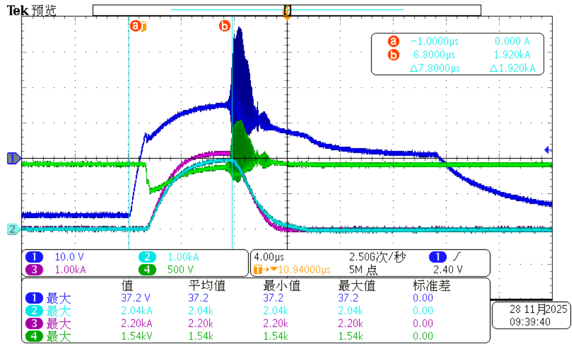
RGon=3.75Ω, significant oscillation
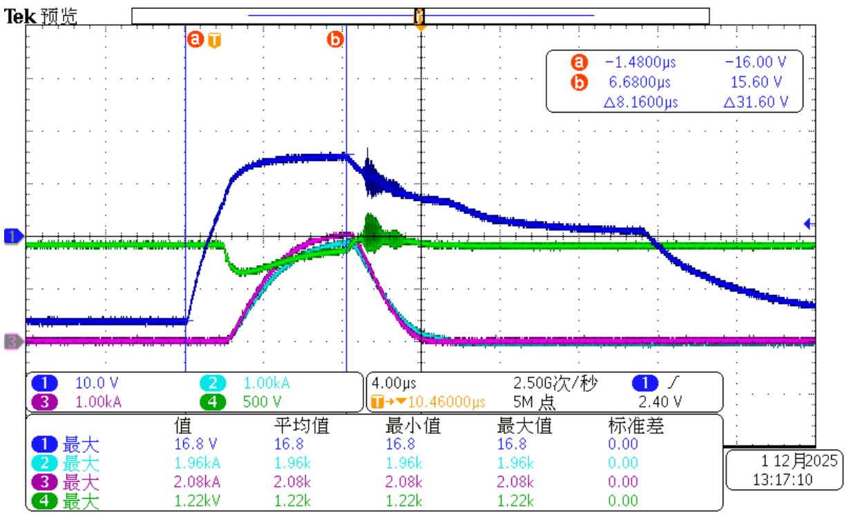
RGon=6.5Ω, Significant suppression of oscillations
III. Selection of Gate Resistance and Capacitance
3.1 Calculation of Critical Gate Resistance
To prevent oscillation, the total resistance of the gate circuit must exceed a critical threshold. Based on RLC second-order circuit analysis, assuming the internal IGBT capacitance CGE remains constant during turn-on and turn-off, the minimum gate resistance RG,min required to eliminate oscillation is:
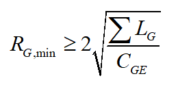
In the formula, ∑LG represents the sum of gate load inductance LG + LGon or LG + LGoff(H), where LG denotes parasitic inductance, and LGon and LGoff are independent lead inductance.
From the formula, it can be seen that if the inductance LG is relatively large, the corresponding gate resistance RG must also be increased to avoid oscillation. Particular attention should be paid to the selection of RGon. If it is too small, the IGBT turns on too quickly. On one hand, this increases the reverse recovery loss of the diode and may even cause the freewheeling diode to exhibit switching behavior, thereby inducing oscillation. On the other hand, it may damage the diode.
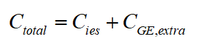
3.2 Function of the Gate Capacitor
Connecting an external capacitor CGE, extra, in parallel across the gate and earth terminals increases the total capacitance of the oscillation circuit:
According to the resonance frequency formula:
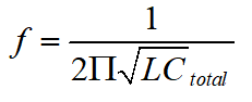
Increasing Ctotal reduces the resonant frequency, thereby helping to suppress high-frequency oscillations.
Summary
Suppressing IGBT gate oscillations requires a comprehensive approach:
- Optimize layout: Shorten drive loops and reduce parasitic parameters.
- Resistor adjustment: Select RG judiciously to balance switching speed and damping.
- Absorption design: Employ non-inductive capacitors to suppress voltage spikes.
- Capacitive compensation: Where necessary, parallel CGE and extra capacitors to alter resonance characteristics.
Implementing these measures significantly enhances system stability, ensuring long-term reliable operation of the IGBT.
References
[1] Infineon. IGBT Drive Current Behaviour Overview.
[2] Infineon. IGBT Modules: Technology, Driver and Applications.